
.jpg)
Sensitivity:
Requires +/-15V DC regulated (lab) power supply, available as our Model 914 controller which contains the driver card integrated with +/-15V power supply.
Input +/-5V gives +/-25V (50V swing) output to piezo wafers.
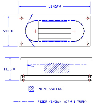
| Length | 4.0 inches |
| Width | 2.0 inches |
| Height with conn. | 1.75 inches |
| Fiber Length/turn | 220mm |
This device has application to thermal stability in fiber optic interferometers.
This is essentially a mechanical device with a mix of ceramic and plastic components.
The plastic, especially the primary buffer on the fiber and the resin that bonds the fiber to the piezo wafers, gives a relatively long mechanical time constant.
This plastic also absorbs energy at high frequencies and transmission of motion from the piezo to the fiber is damped.
There are resonances throughout the DC to 50 kHz range with a particularly strong one around 40 kHz.
The frequency response characteristic below shows the stretch in microns vs. +/-5V applied sinusoidal voltage input (input to our standard driver card). It is different for each fiber jacket type and varies somewhat with the individual assemblies.
The 915 can be modulated by a partial fringe for signal detection systems that use phase and quadrature or max min arrangements up to 50kHz but the phase will be dependent on the resonances and frequency.
The application of the 915 is in a closed loop where a servo error signal can be applied to a correct the phase (or for example track a fringe minima) of the signal. Feed forward compensation will improve the tracking response, but it is limited by the mechanical time constants of the plastics to about 100 Hz.
In open loop the 915 will show drift due to thermal changes and stress relaxation.
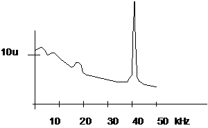
The figure shows a typical response characteristic for approximately 5m of fiber or 25 winds.