|
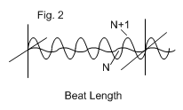
Plane polarized light launched on one axis will maintain the state of plane polarization and follow the bends of the fiber along that axis. The polarization is maintained because the difference in propagation constants of the slow and fast axes is relatively large, which tends to cause any cross coupled light caused by twisting, to destructively interfere within the beat length. The beat length is defined as the distance that is traveled to bring the fast and slow axes back into phase. This is analogous to a full wave plate. |

Polarization Extinction Ratio ( PER ) = 10 log I_f /I_s expressed in dB where I_f and I_s are the intensities in fast and slow axes. For example if 0.1% of the light is cross coupled
PER = 10 log 0.1/100 = -30dB
<table align="center" border="0" cellpadding="1" cellspacing="1" class="wrap-cells-table" "="">
The program PMFiber shows the state of polarization along a length of PM fiber as it is twisted or rotated cyclically.
Fiber optic devices fabricated in PM fiber all suffer to some degree from cross coupled light from the slow axis (usually the principal axis) into the fast axis. This is caused by external stress or modification of the fiber structure. The quality of polarization preservation is quantified as Polarization Isolation, or
 |
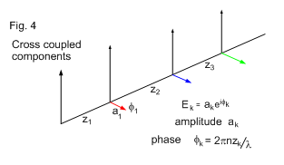 |
several devices along the same fiber path, Figures 3 and 4, the individual cross coupled components, amplitude *a_1 , a_2 , a_3 * will interfere with respect to their phase. Amplitude is the square root of the Intensity and is the fixed quantity that is the property of the device; phase is a variable dependent on the fiber path length and varies with the temperature of the fiber.
At a given temperature, the output PER ( as intensity) of a cascaded string is the sum of the amplitudes with respect to the phase at that temperature, (all squared). This is shown graphically in Figure 5.
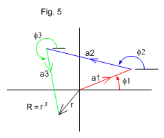 |
In complex notation a cross coupled component is written as E=ae^if amplitude a, phase f For several cross coupled components the resultant is the sum of these individual components with respect to phase. The vector diagram in Figure 5 illustrates the resultant for three devices in series where the intensity R is the final amplitude r^2 . As the phase angles f are variable as a function of temperature it can be seen that the resultant * R* can be any value from zero, to a maximum * r = a_1 +a_2 +a_3 * when all phases are equal as shown in Figure 7. |
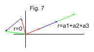
The program Cascade shows the output for several devices with various phase and amplitude choices.
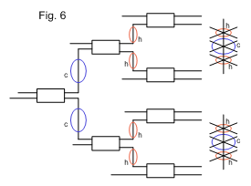
In trees such as 2 to 8 splitters, Figure 6, that have strings of two and three couplers in series, this effect is observed as a random distribution of PER in the eight outputs. For example, with devices that have average isolations of -24dB, the PER in each channel can vary, typically from -30dB to -18dB.
An output polarizer will reduce the cross coupled component to a negligible level, but this does not change the light intensity in the principal axis which has been reduced by the cross coupled amount. Temperature changes that change the phases of the cross coupled components still affect the principal axis light intensity.
