We are taught that "Light travels in straight lines" as "rays" and this is a valid statement for traditional geometrical and physical optics where light propagates linearly in bulk media. Light is also described as a transverse electromagnetic wave composed of an electric vector (E) and orthogonal magnetic vector. The energy in a light beam may be described by the E field distribution orthogonal to the direction of propagation.
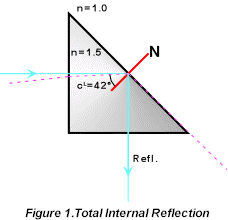
Total internal reflection (TIR) occurs when light travelling through a medium is reflected from the interface with a less dense medium at an angle exceeding the critical angle. The 90 degree prism of Figure 1 is a simple example of this effect.
As a convex surface of similar density material is brought into close proximity to the reflecting surface, there occurs some transmission of light leaving a partial internal reflection, as in Figure 2.
 |
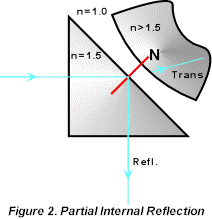 |
This demonstrates that there is an evanescent energy field outside the cube material allowing interaction of the two surfaces across the small air gap.
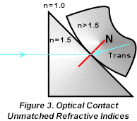
If the surfaces contact (see Optical Contact) as in Figure 3, all the light is transmitted as a refracted beam. If, as in Figure 4, the media have the same refractive index the surface effectively disappears and the ray is unbent showing no refraction.
 |
 |
|
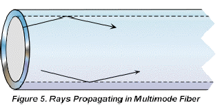
In multimode fiber, which has a relatively large denser core diameter, the modes may be considered to be numerous traditional rays as in Figure 5. For a detailed analysis the reader is referred to Hunsperger, R.G., _Integrated Optics: Theory and Technology Second Edition_, Springer-Verlag, New York, 1984, p. 24. A transverse wave propagating in the positive /x/ direction has the equation: Y= /a/ sin {2ptn - b/x/}where /a/ is the amplitude, t is time, n is the frequency and b a propagation constant, defined as 2pn/l, where l is the wavelength and n is the refractive index of the medium. |
 |
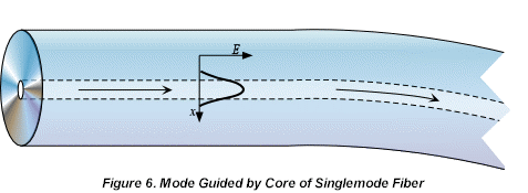
Guided Waves occur when light propagates along or is constrained by the physical boundaries of a waveguide. This is the case for a singlemode fiber where the denser core has refractive index n1 and the cladding is less dense with refractive index n2. When the core diameter is small enough that the number of possible totally internally reflected rays is reduced to one, thus allowing only a single mode of guided light, the concept of rays changes to modes which bend with or are guided by the core, as in Figure 6.
The propagation constant has a value 2pn1/l < b < 2pn2/l, where n1 is the index of the core and n2 is the index of the cladding.
For cores of intermediate diameter that support several modes there are a range of b values. The energy in any one mode is distributed between the core and the cladding where that in the cladding is called the evanescent tail.
Eigenmodes (Supermodes) and Coupling
Consider two parallel singlemode waveguides in close proximity. If the evanescent tails of each waveguide have considerable overlap, it can be shown that there are two possible solutions for mode propagation in the two waveguide structure. These are the Supermodes or Eigenmodes. The two solutions have symmetric and antisymmetric energy distributions and differing propagation constant (b) values.
As the relative phases of the modes change the energy is shared between the two waveguides and at matching and mismatched phase the energy is alternately maximized in each waveguide. i.e. the energy beats back and forth between the waveguides, dependent on the waveguide separation and the interaction length. This gives the term "evanescent wave coupling".
b matching and over coupling
The polished evanescent wave coupler is based on bringing the cores of two fibers close together by removing part of the cladding and optically contacting the polished faces. By this process, the two cores behave as if they are contained within the same cladding.
Bent in their supporting substrates to allow fabrication, the cores are not parallel, so the coupling is progressive as the cores become closer. The interaction length and core separation are therefore averages or estimates.
A 3dB coupler is one which is made such that the energy is shared equally. In percentage terms this is a 50/50 split. A 100% coupler is where all the energy has transferred from the input fiber to the secondary output fiber. This is the first beat condition and is constrained by the matching of the individual b values for the polished fibers in the interaction zone. This would imply that the polished surfaces have identical refractive indices at the contact if identical fibers are coupled. As polishing a fiber and removing cladding changes the refractive index profile of the fiber 100% coupling is sensitive to polishing depth.
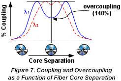
Overcoupling is defined as greater than 100% when the interaction length or core separation allows the first beat to be exceeded. A 150% coupler is therefore equivalent to a 50% coupler but shows increased wavelength dependence, as shown in Figure 7.